0. What is this document
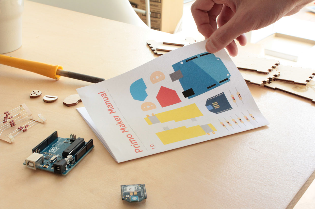 This document gathers and organizes all the information necessary to build a Primo Prototype.
You can find more info about the project on the primo.io website.
This document gathers and organizes all the information necessary to build a Primo Prototype.
You can find more info about the project on the primo.io website.
How to translate this document
If you want to translate this page in your language, you have multiple options:
-
super easy, no automation Copy and paste this page in your text editor, translate it then mail it to us at play@primo.io
-
medium, light automation Create an account on GitHub, then open the repository of this page and click on ‘EDIT’, in the top menu bar:
 Then your page turns into a text editor, where you are able to modify the page source. The page is written in markdown, very easy to understand.
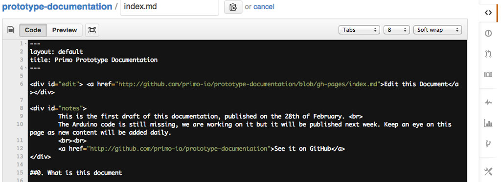 You don’t have to modify this code, but just copy and paste the whole text in your local text editor, then translate the textual parts in your language, without modifying the parenthesis and HTML parts. Save the text then mail it to us at play@primo.io
 -
advanced, full automation This is slightly advanced, but nothing too hard, if you are not familiar with GitHub you have the chance to learn something new :)
If you are already familiar with git, you have to fork the repository, all the translations are located in the ‘languages’ folder. To translate the page, just copy it with the starting language (“english.md” for example) in the same folder, then change the file name with the final language (spanish.md). Change the page header values ‘title’ (title in your language) and ‘language’ (the destination language with Capital letter) then translate the rest of the document. Once finished, make a pull request to add your file to the folder, it will be automatically added to the menu.
The steps above, expanded: - Make a GitHub account
- Download the GitHub application (Mac, Windows)
- If it’s the first time you use it, open it and input your GitHub login details
- Go to this documentation repository
- Click on the “Fork” button in the top right corner, to fork this repository into your account.
- Go to your giHub account, open the forked repository page and click on the “Clone in Desktop” button, on the right-hand sidebar. It will automatically open the GitHub application, asking where to save the local repository.
- After selecting a folder path in your computer, click on “clone”
- After downloading the files, navigate to your local folder where the repository has been downloaded.
- Open the ‘languages’ folder, where all the translations are located. Select the starting language (“english.md” for example), then copy the file and rename it to your destination language (“spanish.md” for example), in the same folder.
- Open the newly created file, change the page header values ‘title’ (title in your language) and ‘language’ (the destination language with Capital letter), then translate it to your language, keeping the markdown formatting
- After the translation is completed and saved, it’s time to re-upload it on GitHub. Open the GitHub application and double click on the repository. On the left sidebar, click on the “Changes” tab. It should say “Uncommitted Changes”.
- Give a title to your edits, like “spanish translation”, then click on “commit” and then on the “sync” button.
-
Go to your GitHub profile, on the forked repository page. You should be able to see your newly created page in the ‘languages’ folder. On the top, there should be a green button with two arrows, click on it to issue a pull request. (see picture below)
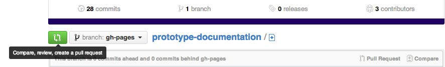
- Then click on “Create Pull Request”

- Write a message for the pull request and that’s it! Now we just have to approve the request.
1. What is Primo
Primo is a tangible interface designed to introduce programming logic to little children (3 to 7), without the need for literacy. The goal of the game is to drive a little robot called Cubetto back to his house. To accomplish the goal, children have to program the little robot using a limited set of instructions: forward, left, right and function. While the first three are rather intuitive, the last one calls a sub-routine, an extra line of instructions packed in a single command.
2. Research
Teaching programming to children is a widely debated topic. We are aware of a moderate number of solutions that try to accomplish this for children above the ages of 8. However, there aren’t many of these solutions suitable for younger children, and there aren’t any that work without a screen or without the need for literacy. We see an increasing number of Apps for tablets and computers that also work in combination with physical robots, but none of them are completely free from the pixel domain in the same way the Primo Play Set is.
Wood was chose as the main material, first of all because it’s natural; you get a warm feeling from it and it makes a nice sound. The second reason is cultural. Observations were conducted on games used in traditional kindergartens in Switzerland (where the product was originally designed) to discover that the games loved by children were all made out of wood. Wooden toys are very durable and you can see marks and scratches on them, signs of their past usage from other children. It’s a material with memory. Wood was also chosen as a material because of the stark contrast it creates with technology. Inside of Primo there’s a circuit board, but we wanted to create a “magical” experience, hiding the complexity of the play set.
![]()
The concept behind Primo is heavily inspired by the work of Seymour Papert, a mathematician who co-founded the MIT Artificial Intelligence Laboratory with Marvin Minsky, in the sixties (if you are interested in the subject, we encourage you to read Mindstorms, his most famous book). He was directing the team who invented LOGO, probably the most used and long lasting resource to teach programming to children. The goal of Seymour Papert was not just to teach code, but also to help children discover their own personal way of solving problems. Primo can be considered an extreme simplification of LOGO and the physical turtle. We limited the instructions, to their purest form, avoiding any kind of textual or numerical language.
The first prototype was realised in SUPSI Lugano by Matteo Loglio (Primo.io co-founder and interaction designer), during the MAInD - Master of Advanced Studies in Interaction Design. Matteo’s background is in product design, and after learning the Arduino basics and a bit of code to create the prototype, began to look around for technical solutions that were approachable for a novice, so as to develop an application like Primo. The main issues were two: making a robot car from scratch and an interface board that could easily recognize different instructions.
The first issue was solved by using an Oh_Oh board from David Cuartielles, one of the Arduino founders who was holding a lecture in SUPSI. The Oh_Oh robot is an open project, you can find the source files in the link above. It is basically a car shaped Arduino, only an XBee for radio communication was added.
The second issue was designing a reliable way to detect the blocks. A solution was inspired by a CIID project called “Barcode Piano”.
The idea is to use multiple blocks that can be recognized by a board using resistors. It’s a basic voltage divider, with the analog pins of an Arduino reading the resistor values. It’s a very simple method, but rather effective for a prototype.
Design-wise, some features required testing; the actual design is the result of several iterations.
The ‘snake’ or ‘zig-zag’ path of the instruction sequence was chosen to avoid literacy pre-conceptions.
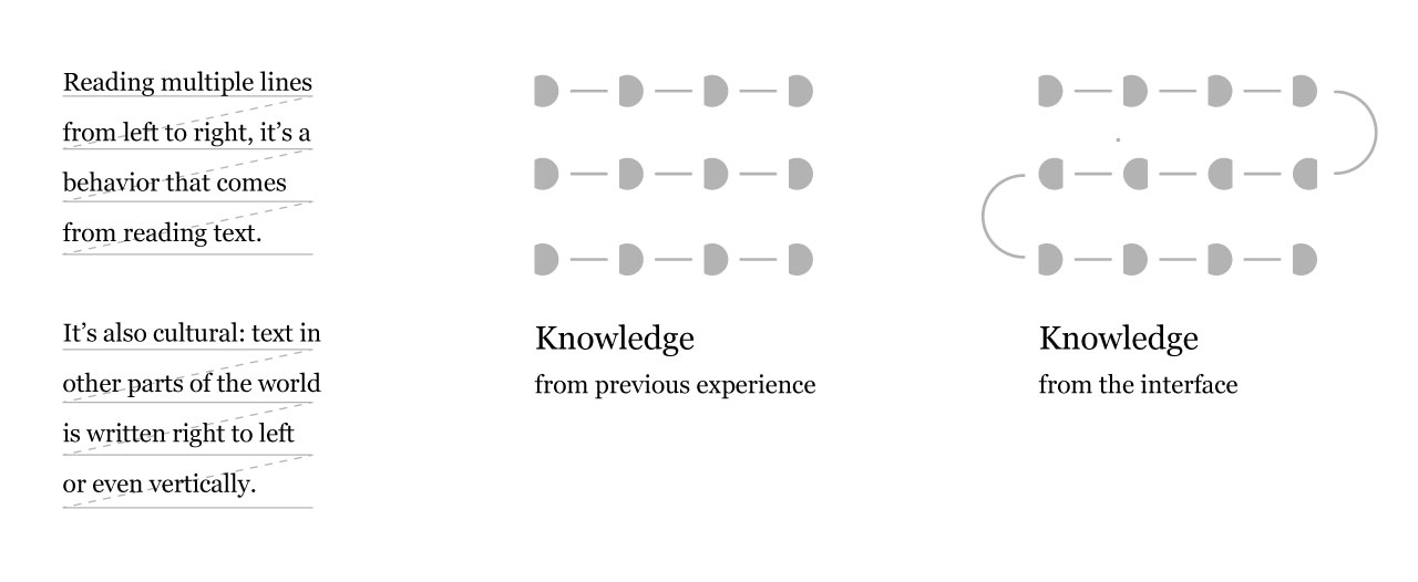
The ‘D’ shape of the block connectors, was designed so that blocks could be inserted just one way, to be consistent with the path design and the direction of the car. Multiple designs can be used for this. The D shape was chosen as it is basically an ‘oriented circle’ and as a shape, also recalls similar pin-board designs.
The design for the shape of the instruction blocks is still being tested. The actual design works quite well, children easily grasp their meaning, they just have some troubles at the first to get familiar with the left and right block. This is also because the “right” and “left” concept is generally quite new for them. We are currently testing other blocks design, to improve this even further.
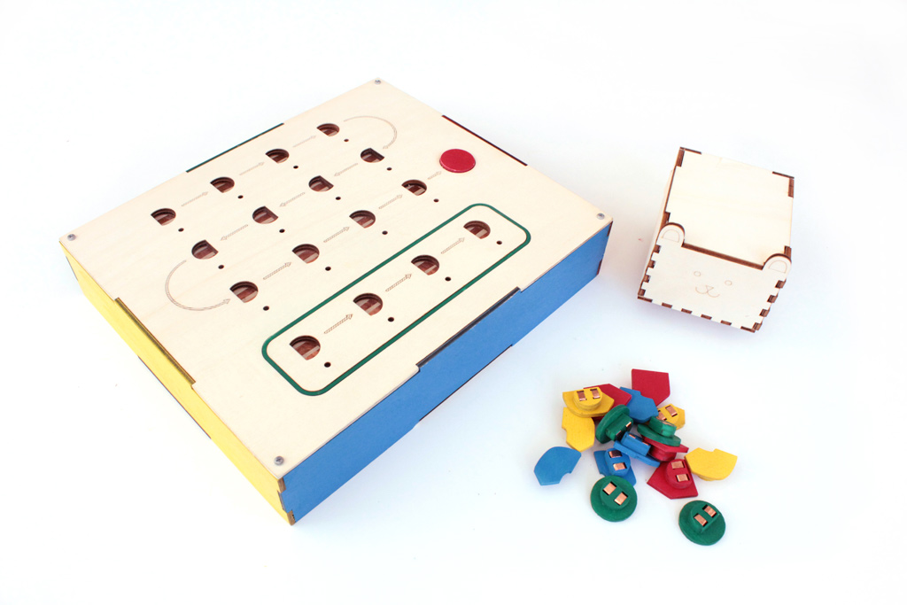
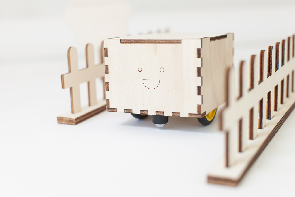
At the beginning the robot was a toy car. A very complicated and time consuming shape to produce, as it’s a laser-cut shape glued together layer by layer, and subsequently sanded for over an hour. The car had another major issue, it was very boy oriented. We wanted to avoid entering in discussions about ‘brain toy’ producers being criticised of only producing boy-oriented toys. We wanted to stay neutral, we didn’t want to create a toy specifically for boys or girls, and instead opted for a very neutral geometry, a box.
A name was given to the little box, along with a personality and a similey face, making it even more appealing for children. The robot is called Cubetto (little cube in Italian). The idea with Cubetto is also to create a basic module that can be expanded and customized easily in the future.
3. Getting Started
3.1 The basics
Primo is composed of three parts: An Interface Board, Cubetto and a set of Instruction Blocks. Children interact with the Interface Board by placing Instruction Blocks into the holes, to create a sequence (A program) that Cubetto executes.
There are four types of Instruction Blocks, this means that resistors of 4 different values can be used, possibly quite distant between each other.
The blocks are inserted into the holes of the Interface Board, where the resistor value is identified. After that, the values are processed into a string that is sent to Cubetto using two XBee modules. Cubetto then executes the instructions, one after the other.
The brain of the prototype is made of two Arduino Boards, a UNO (A Leonardo or a Duemilanove will also do) for Cubetto, and a Mega for the Interface Board, where 16 analog inputs are required.
3.2 Electronics
Tools Required
- Soldering Iron
- Solder
- Wires
- Hot Glue Gun
- Wood Glue
- Copper Tape 5mm wide
Materials (prices in euro)
Cubetto ~ 88 €
- Arduino UNO (or Leonardo) - 20 € : Arduino Store
- Arduino Proto Wireless Shield - 14.90 € : Arduino Store
- SN754410 Motor Driver - 3.90 € : Arduino Store
- XBee (series 1 or 2, doesn’t make any difference) : 23.90 € - Arduino Store
- SolarBotics Wheels x 2 : 4.74 € - Solarbotics Store
- SolarBotics Gear Motors GM3 x 2 : 8.36 € - Solarbotics Store
- 2 Ball Casters : 5.79 € - Solarbotics Store
- CNY70 x 2 : 1 € - Mouser
- (optional) Battery Holder : 4 € - Solarbotics Store
- (optional) 4 x Rechargeable Batteries
Interface Board ~ 88 € (pure coincidence)
- Arduino Mega 2560 : 39.00 € - Arduino Store
- Arduino Proto Wireless Shield : 14.90 - Arduino Store
- XBee (series 1 or 2, doesn’t make any difference) : 23.90 € - Arduino Store
- 16 5mm Red LED : 1 € - Mouser
- 16 220 Ω Resistors : 0.16 € - Mouser
- 16 10K Ω Resistors : 0.16 € - Mouser
- 1 Push Button : 1 €
- 50 Male Headers : 1 €
- 16 Double male headers : 0.50 € - Arduino Store
- 50 female headers : 1 € - Arduino Store
- 16 Magnets ø 4 h 3 : 3.5 € - Supermagnete
Instruction Blocks ~ 4 €
- 4 x 4.7K Ω Resistor : 0.04 € - Mouser
- 4 x 100K Ω Resistor : 0.04 € - Mouser
- 4 x 220 Ω Resistor : 0.04 € - Mouser
- 4 x 10K Ω Resistor : 0.04 € - Mouser
- 16 Magnets ø 4 h 3 : 3.5 € - Supermagnete
3.3 Energy
Cubetto and (optionally) the Interface Board, are battery powered. For the prototype you can use a LiPo battery or regular AA batteries, that’s entirely up to you. We used both, LiPo batteries are good but you need extra equipment, if you are starting from scratch we recommend AA batteries. Just remember they run out very quickly, so the best would be to use rechargeable batteries, like NiMh.
3.4 Prototype Design
The whole product is made out of laser cut wood, mainly 4 mm thick, with only one layer being 1mm thick. You can laser cut these parts using services like Ponoko, or in your local FabLab. The first prototype was laser cut inside FabLab Lugano, while the product development advanced in FabLab Torino, where part of Primo development team still resides.
Building Cubetto and the Interface Board is a laborious but very simple procedure, their shells are basically boxes. The real complexity lays in the Instruction Blocks. They are a double 4mm wood layer with magnets and resistors soldered inside.
4. Prototype Making
Download Source Files
4.1 Interface Board
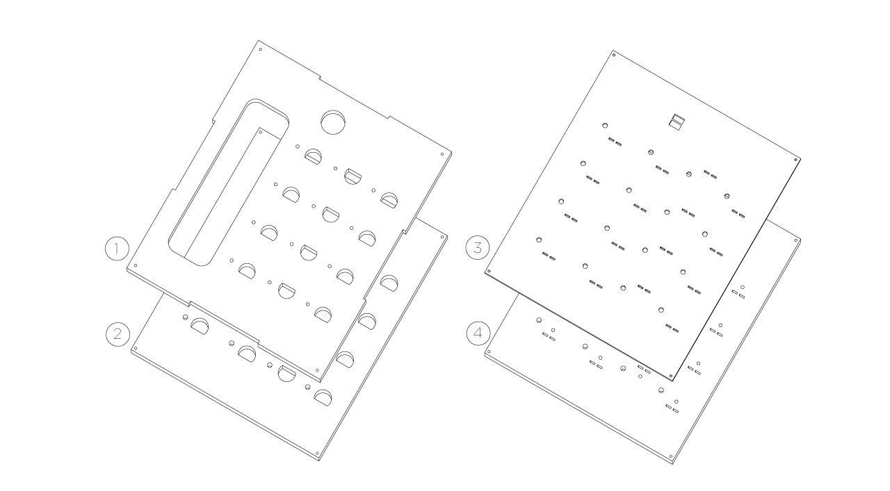
To make the interface board you have to laser cut two files: interface-board-4mm.dxf and interface-board-1mm.dxf: the first one is for 4mm plywood and the second one for 1mm plywood. As you can see from the files, the parts are numbered, to ease the assembly process. The numbers are stored on a different layer, so you can easily remove them before lasering. We recommend adjusting the hole for the push button, based on the size of the button you wish to use or have.
First of all, you have to glue parts 3 and 4 together, use the holes in the corners to align them with screws while gluing and let it rest for a night.
Then take the copper tape, cut 32 pieces of 70mm each and put them inside the rectangular holes in the part that you just glued, they should be at least 30mm wide on each side. Once you finished, you can now glue all the remaining top layers of the interface board, this is the correct order:
Then take the copper tape, cut 32 pieces of 70mm each and put them inside the rectangular holes in the part that you just glued, they should be at least 30mm wide on each side.
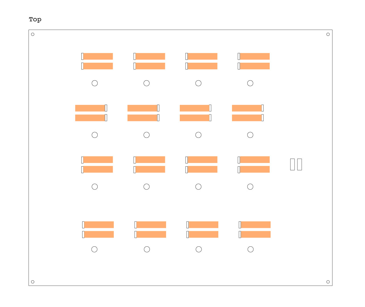
Once you finished, you can now glue the previously glued parts, 1+2 with 3+4.
Once the glue has dried, put the magnets in the little holes. Turn your top layer upside-down and fill the little holes with the magnets, make sure they are all in the same direction, doesn’t matter if north or south. Seal the hole with a drop of hot glue.
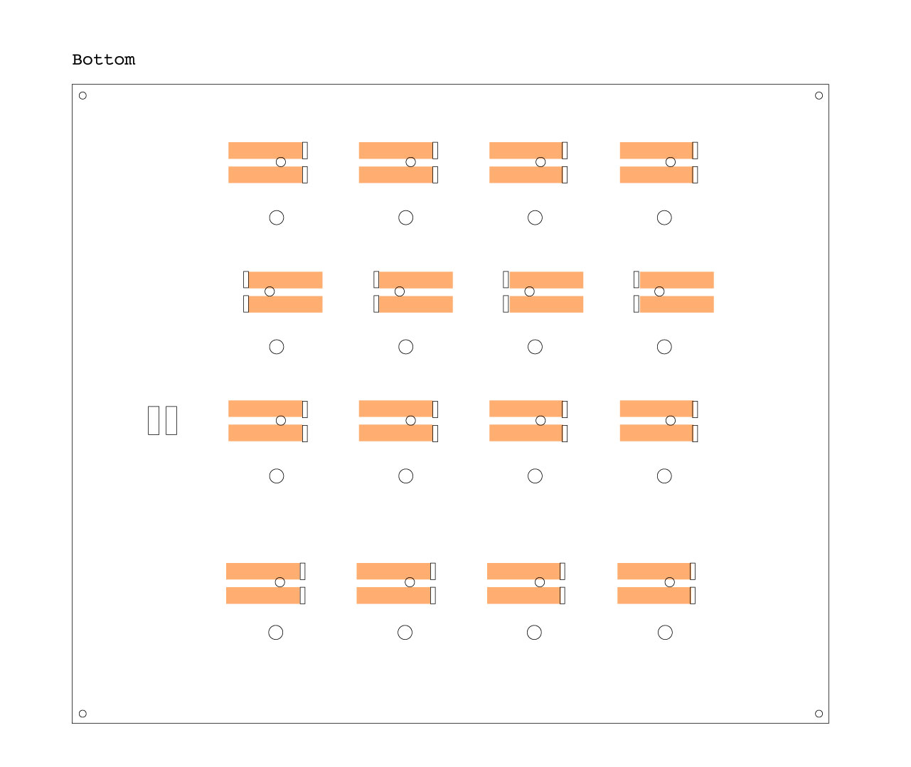
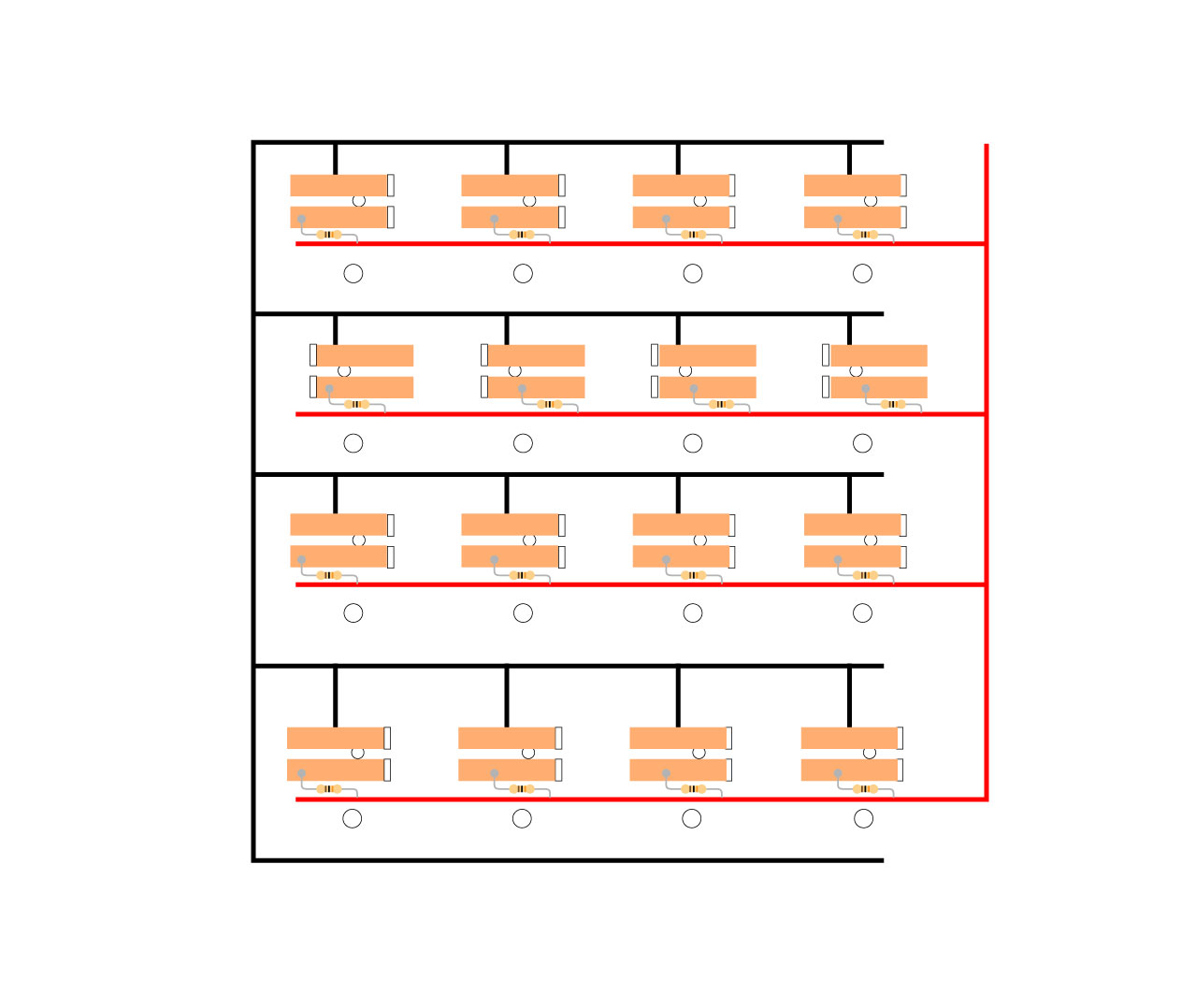
Now the electronics. Start by making rails for the 5V and the GND, all along the hole lines like in the picture. The first ever prototype never had copper strips, it had wires (which you can also use), but in this prototype we used copper tape also for the rails. A real 100% time saver. It also makes things easier for creating connections.
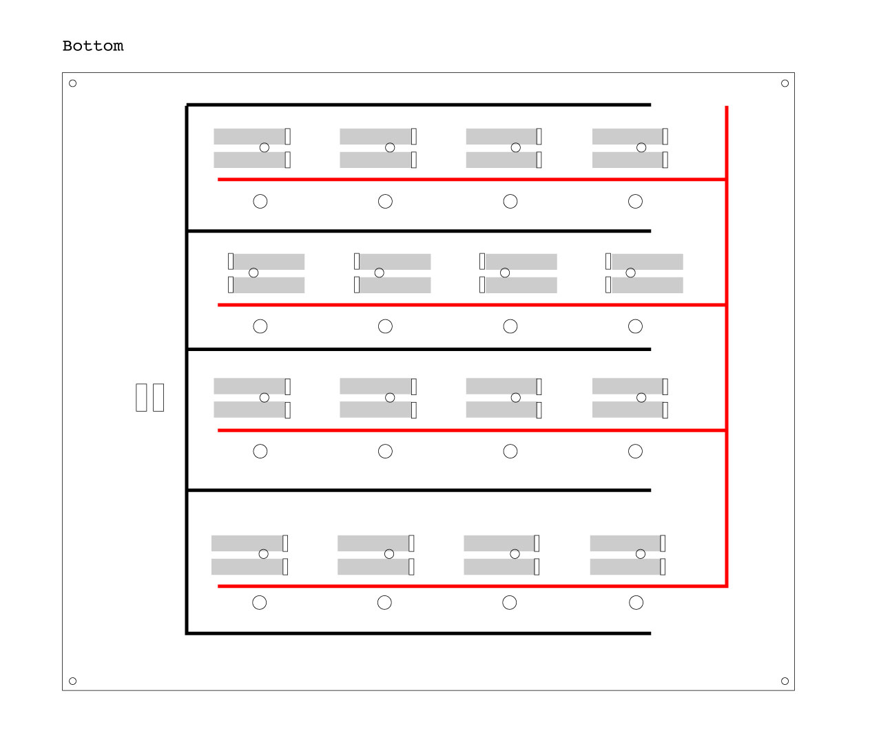
The next step is to wire one of the two connectors of every hole, to the ground rail. If you used copper tape, you can just use a tiny extra bit of it, just enough to touch both ends.

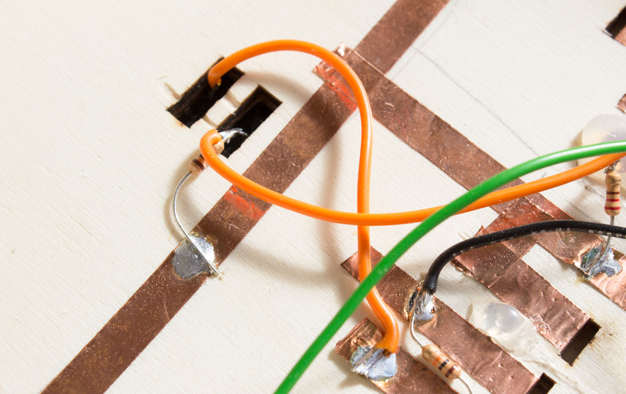
Now we have to connect the other side of each connector to the 5V rail, but this time, with a 10KΩ resistor in-between. A cool thing of copper tape is that solder melts very well on top of it. This is the technique used:
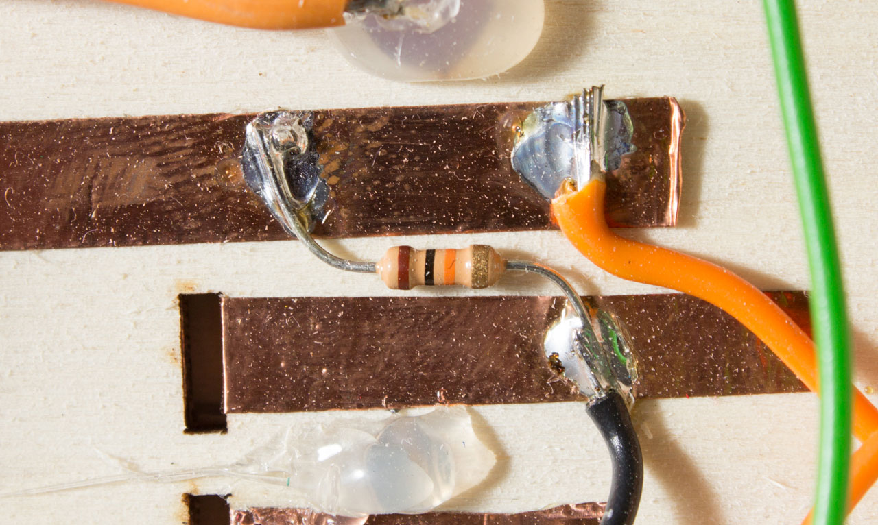
At the end of this process, you should have something like this:
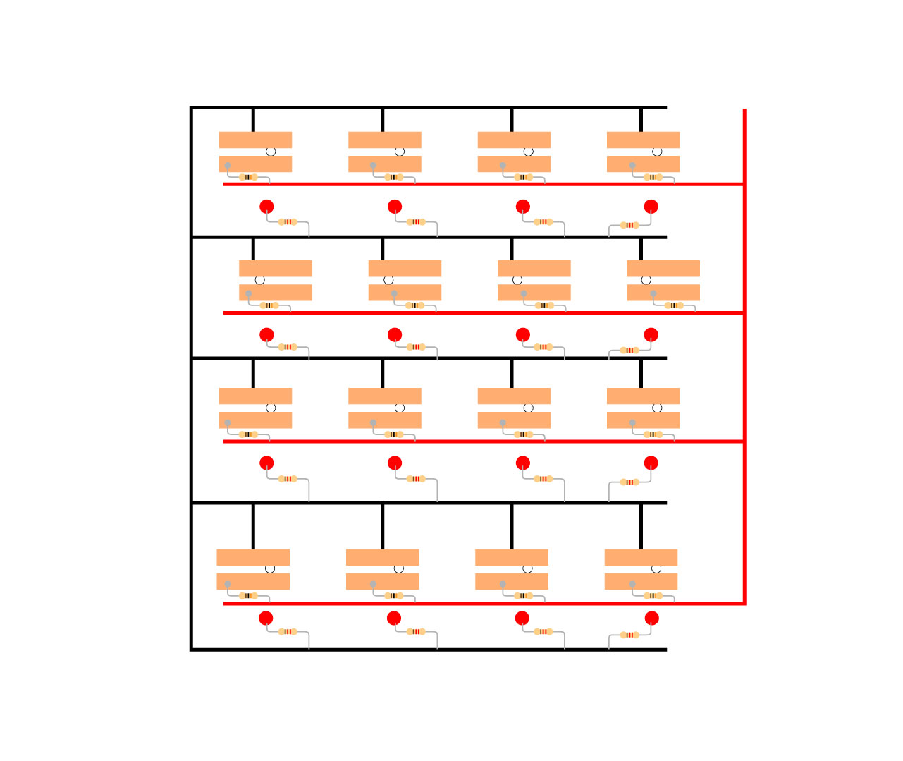
Now it’s time to put the LEDs; stick one red LED in each one of the 16 holes, then use a drop of hot glue to seal them to the wood. Once the glue is cold, we have to connect them. Just mind that LEDs have a polarity: the long leg is the anode and the short one the cathode. Connect each cathode to the ground rail, using a 220Ω Resistor.
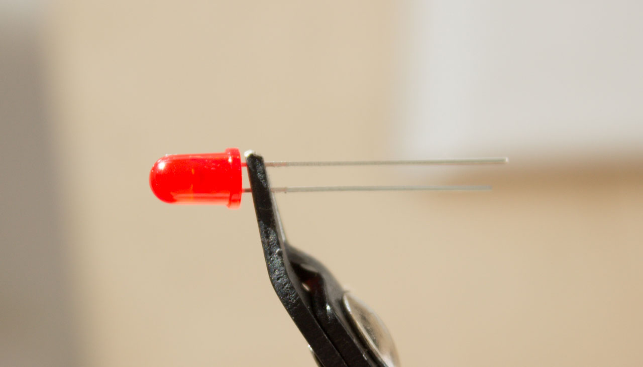
Connect each cathode to the ground rail, using a 220Ω Resistor.
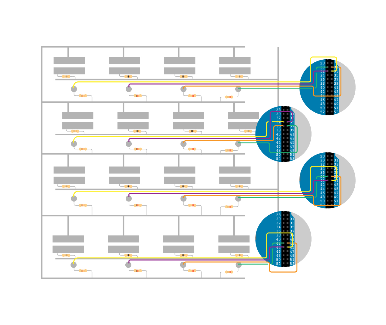
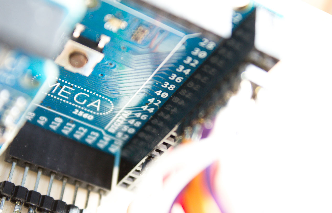
The long leg of the LED, must be connected to a digital I/O pin on the Arduino Mega, these pins are numbered from 22 to 53. The LEDs must be connected in order, so that it will be much easier to access them later on in the code, in my prototype for example I started from pin number 30 up to 45 (there are 16 LEDs). The starting point is not important, as long as they are in the correct sequential order. This means for example that if we start from pin 30, the first LED must be attached to pin 30, the second to pin 31, the third to pin 32 and so on until LED 16 to pin 45.
The cables are soldered to a rack of double male headers, as the digital pins on the Arduino Mega are laid out in a double line. In this way it’s easy to plug and remove the Arduino from the board.

Once all the LEDs are soldered, we have to solder our hand made connectors. These must be wired to the Arduino Mega analog pins, to read the different resistor values. Just like the LEDs, these must be connected in order, starting from A0 for hole 1 to A15 for hole 16. The wire has to start from the same point where we soldered previously the 10K resistor. See the illustration:
Here I used some single male headers, as the analog pins are all on a single line.
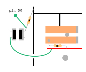
The last thing to connect is the button: take it and solder two cables to two opposite headers, then slip them trough the button hole, from the top, and push it all the way down, until it stops. Now flip the board, you should have the two wires coming out of the hole. Connect them as in the illustration: one straight to 5V, the other one to GND using a 10k Resistor. Then connect it to an Arduino digital pin from the button-end of the resistor, in this example we used pin number 50.
Almost done with the board, now you just have to plug the Wireless Shield on top of the Arduino Mega and stick the headers in place in the board. To recap, 30 to 45 for the LEDs, A0 to A15 for the connectors and 50 for the button. Use the A0 to A5 pins on the Wireless Shield for the first 5 connectors. Don’t forget to connect the ground rail to the GND pin and the 5V to the 5V pin.
Now a little bit of fine-tuning: after that part 12 of the board has been painted, you can glue it with part 13 on top of the board.
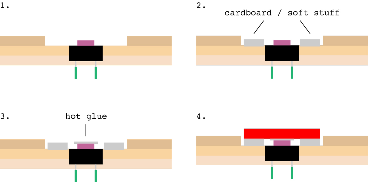
Same for the red button: after part 14 has been painted, put something soft like cardboard on top of part 2, around the push button, then some hot glue on top of the push button and before the glue dries off, place the red button. See the illustration:
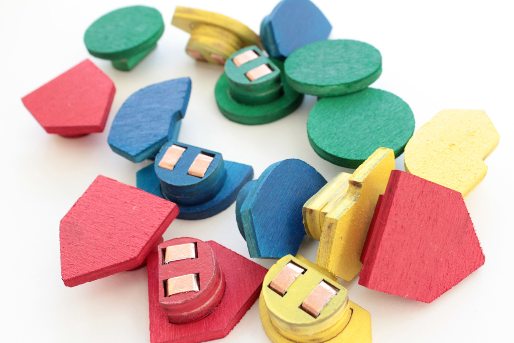
INSTRUCTION BLOCKS
This is one instruction block, exploded:
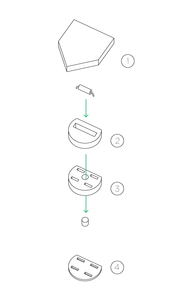
To make the Instruction Blocks, the first thing you have to do is laser cut the files, there’s one for 4mm thick wood and one for 1mm wood. They are four layers, numbered from 1 to 4 and the drawings provided can be used to make 16 blocks, four of each kind.
Each block has a different resistor. These are the resistors used in the prototype:
FORWARD: 4.7K Ω
LEFT: 100K Ω
RIGHT: 220 Ω
FUNCTION: 10K Ω
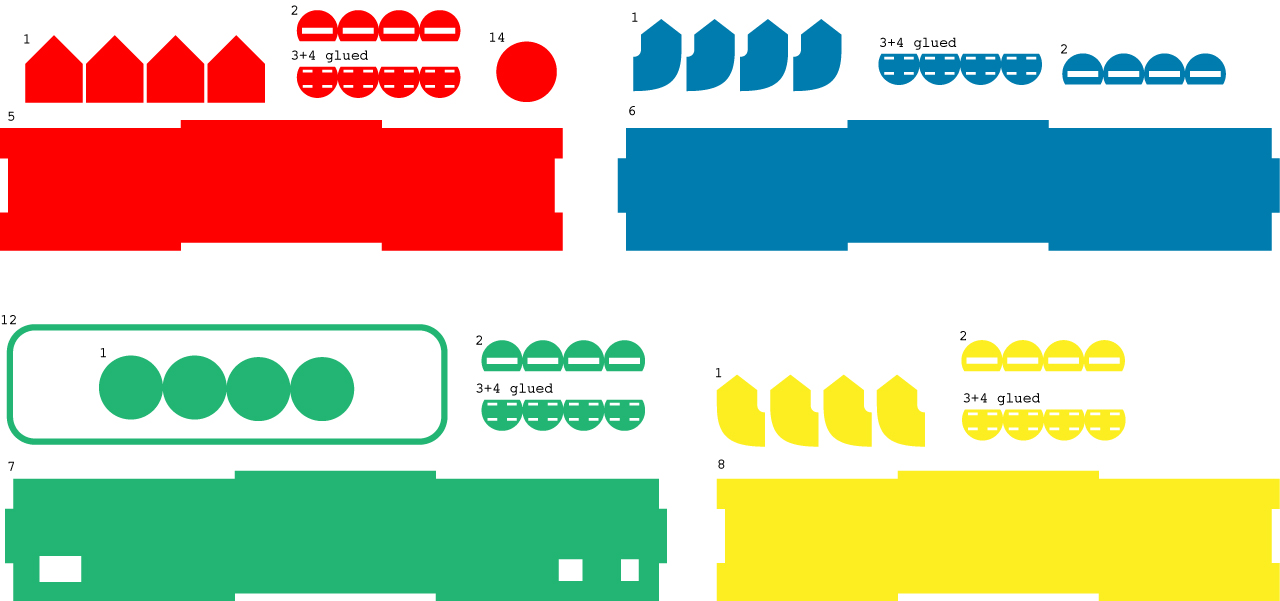
To make blocks, first you have to glue part 4 with part 3.
After the glue has dried, you can start painting. See the illustration below to see what part should be colored:
Now you have to cut two pieces of copper tape, 40mm long. Slip them in the holes of the two blocks that you just glued, making a ring around it using the upper and lower fissure, the ring must be quite tight.
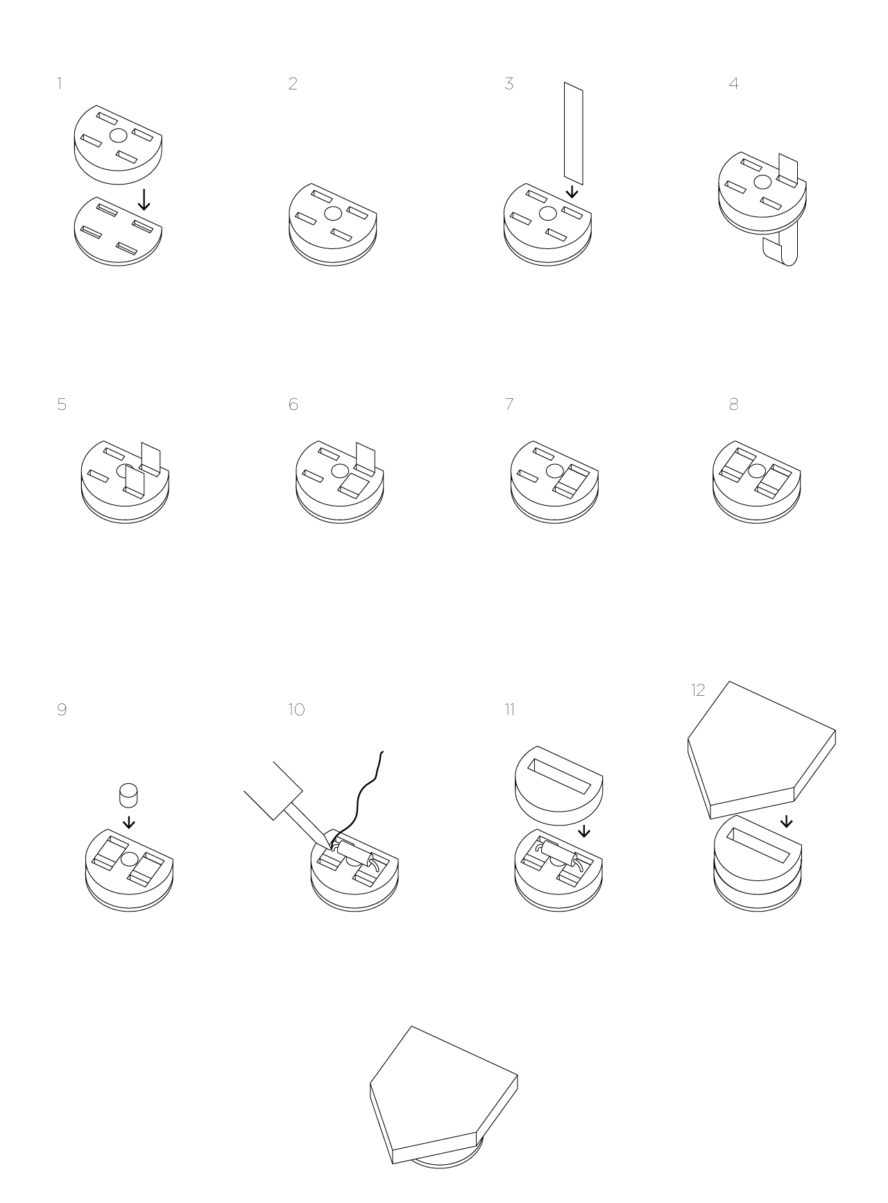
After that, you have to put the magnet in the hole. While doing this, BE SURE THAT IT IS CORRECTELY ORIENTED, so that the block ‘sticks’ into the hole. If you put it the other way, it’s going to be repelled by the other magnet, a funny outcome but not what we want to achieve.
Fix the magnet with a drop of hot glue and before the glue gets cold, put the right resistor on top, with the ‘legs’ laying on the copper tape. After that, the resistor must be soldered on the two pieces. After soldering, cut the extra leg length and glue part 2 on top of the resistor.
Finish your block by gluing the last layer, part number 1, on the top, then repeat the entire process for every single block :)
CUBETTO
Electronics:
The prototype for Cubetto can be built using an Arduino Uno or Leonardo, with a Proto Wireless Shield on top. The reason for the Proto Shield is because it has a small prototyping area, that is wide enough to put the motor driver, the connectors for the optical encoders, motors and power.
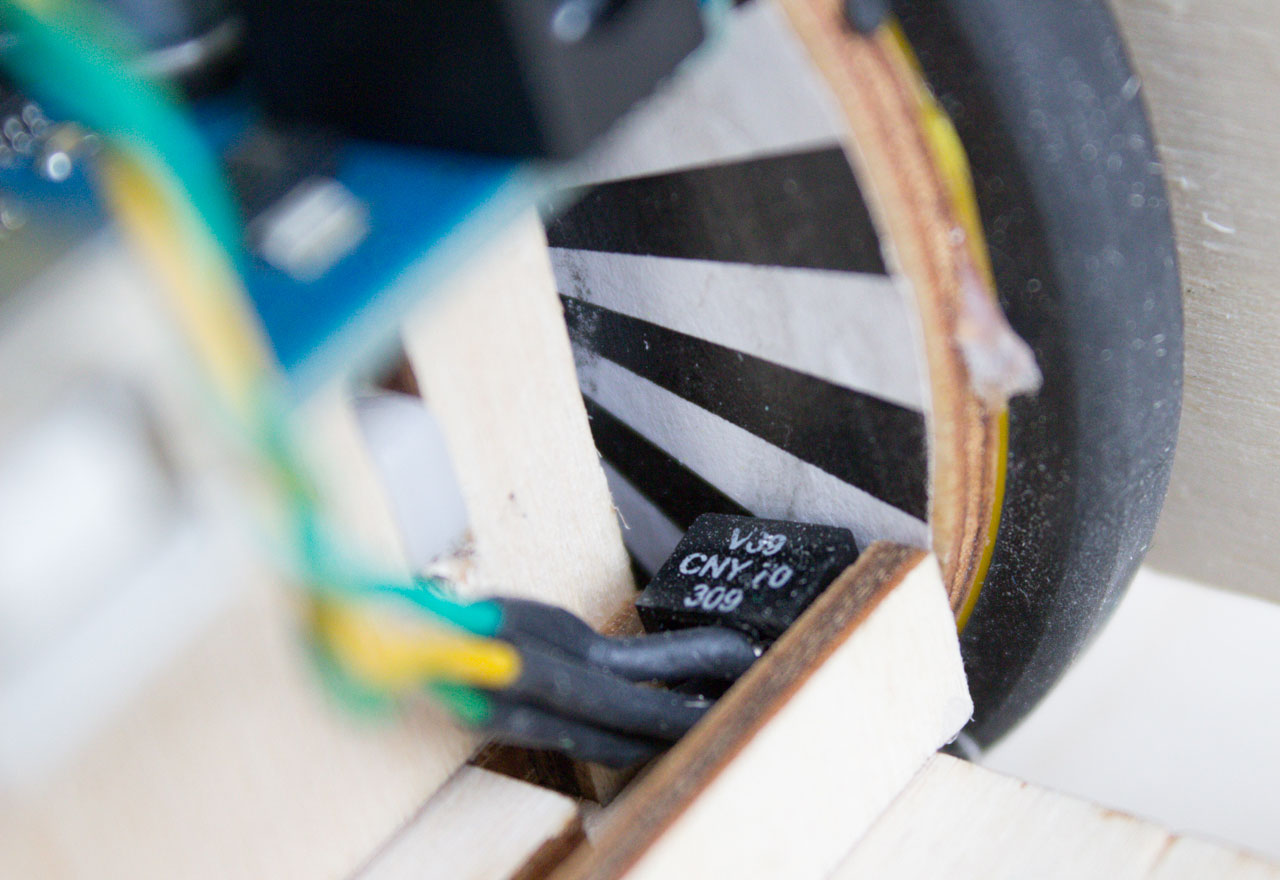
Cubetto has to spin 90 degrees left and right. A very inaccurate way is to use timing event, like “spin right for one second” and you can expect more or less the same result. “More or less” because it depends a lot from different factors, such as the floor, the battery power and so on. The way I solved this problem, is by detecting the amount of rotation from the wheel using two CNY70 optical encoders in combination with a sticker. The round sticker goes in the inner wheel and it’s something like this:
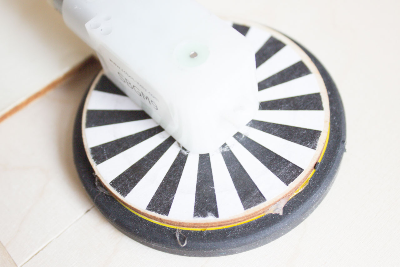
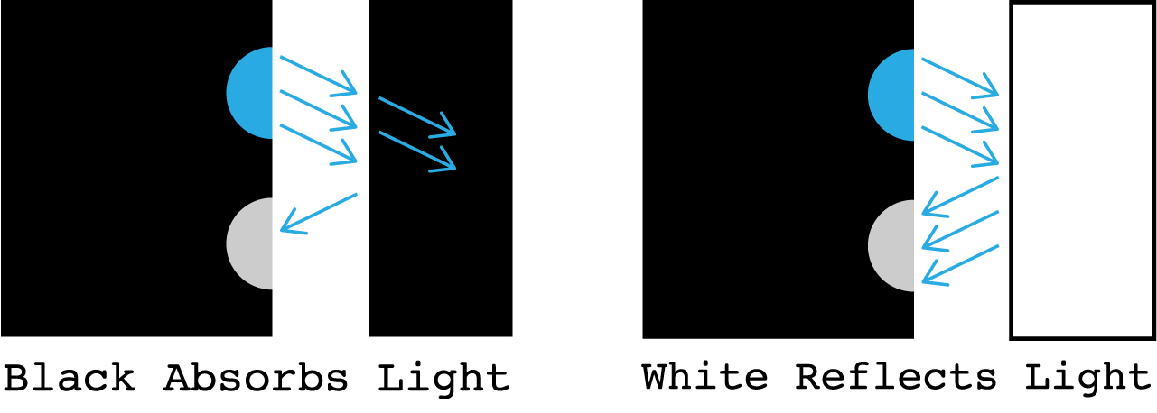
The sticker is split into black and white slices, this is because the CNY70 is able to detect the variation between a white slice and a black one. Basically inside it has an infrared LED that is always on and a phototransistor that is reading the amount of infrared light. When a black material is facing the component, almost no light is relfected, as the black color tends to absorb it. On the contrary, if the material is white, it reflects all the light, so the value read from the sensor it’s very high. The difference between readings is used to count the rotation steps.
The prototyping area of the Wireless Proto Shield is where the motor driver and other connectors for the other parts are soldered. For these, simply use male headers as connector and female headers on the other part.
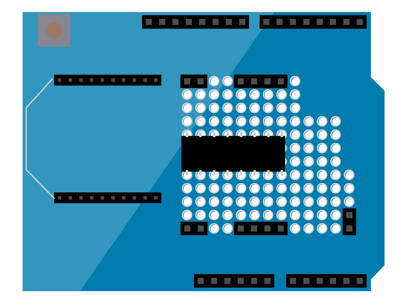
For these I used simple male headers as connector and female headers on the other part.
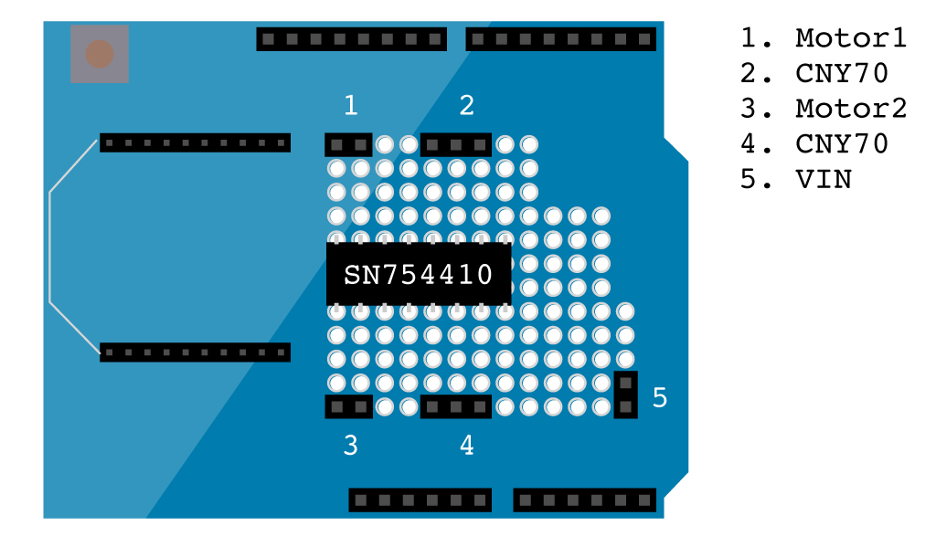
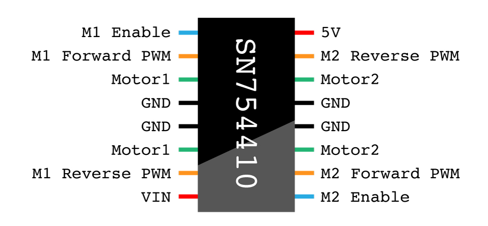
The SN754410 motor driver has 16 pins that must be connected following this scheme:
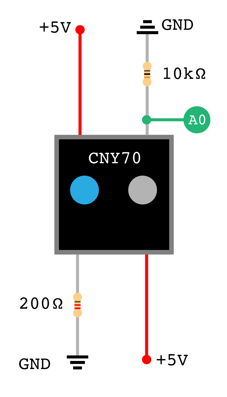
The CNY70 scheme:
Design:
Start by lasering cubetto.dxf; All Cubetto parts are cut from 4mm plywood, follow these visual instructions to build the base:
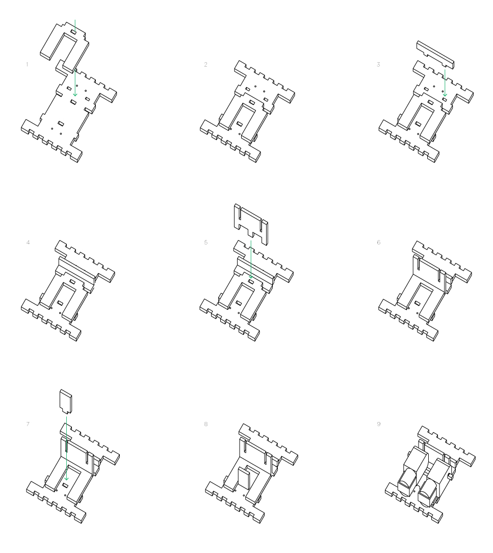
Don’t mount the motors for now, first you have to mount the ball casters.
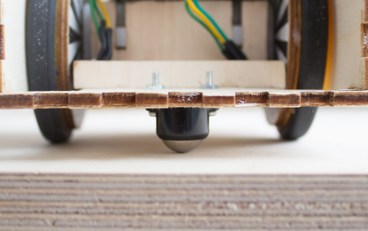
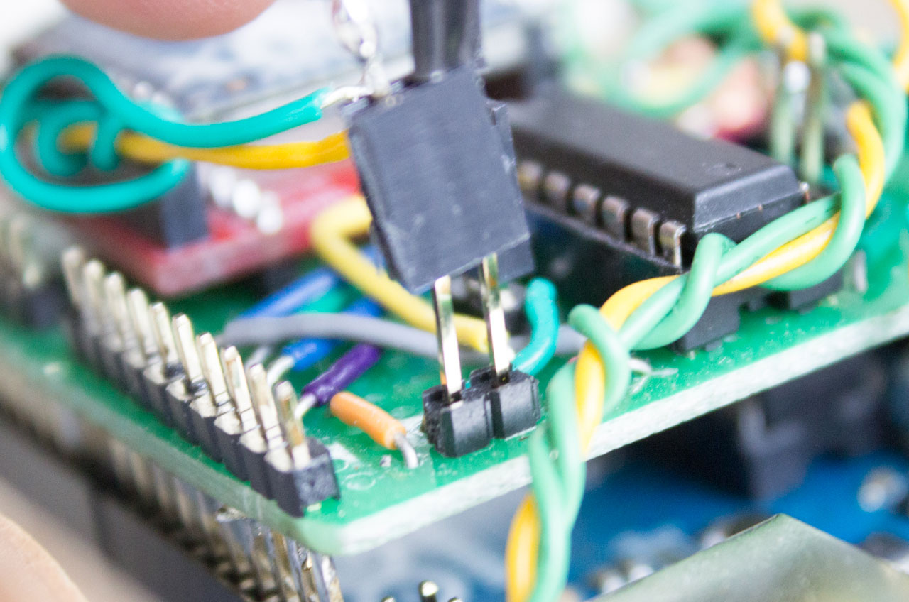
Now the CNY70. Solder the two opposite headers, that must be connected to 5V, together with a wire; then solder three wires to the remaining headers of the CNY70. At the end of these wires solder a row of three female headers. They will later be connected on to the headers of the proto shield.
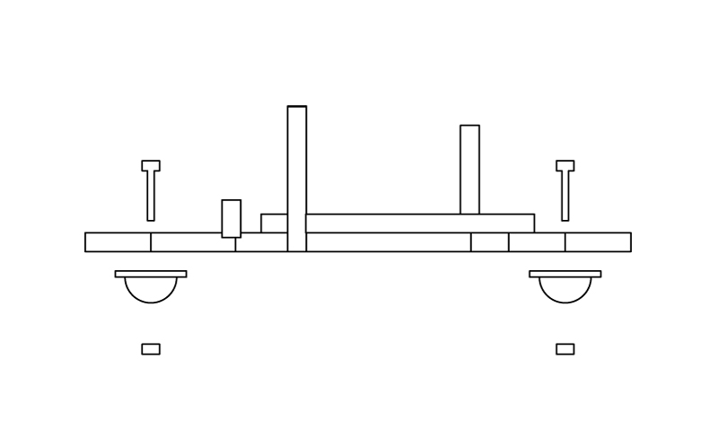
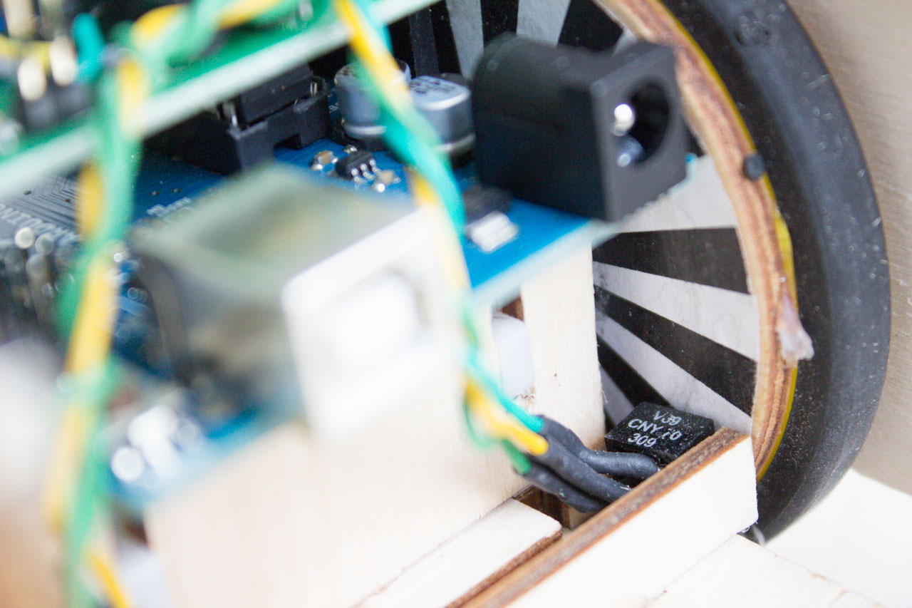
The two cny70 must be placed on the edge of the bottom layer, with the LED and the photoransistot horizontally aligned. To fix them you can use some hot glue (or other types of glue).
See the picture to understand the location.
Just like for the CNY70, solder two wires to the little flaps that come out of each motor. You can twist the two wires to make them more resistent, then at the end, solder a row of two female header, just like in the illustration.
Now print the inner drawing with the black and white slices, glue them on a piece of cardboard (or laser cut wood, that’s up to you), cut the perimeter and make a hole in the middle, as they will be inserted between the motor and the wheel. The white and black slices must point towards the inner side of Cubetto and the distance between the print and the CNY70 must be between 1 and 3 millimeters for the CNY70 to work properly.
Now you can put the wheels on the motors, if you used the Solarbotics wheels, you can fasten them with the screw provided, don’t make it too tight.
Glue three out of the four ‘walls’ of Cubetto, parts 5, 7 and 8. We are going to leave the back removable, just in case we want to modify something.
Take the battery holder and solder the black and red cable to other 2 female connectors. The headers on the shield will go to VIN and ground. A switch that breaks the red wire is heavily suggested.
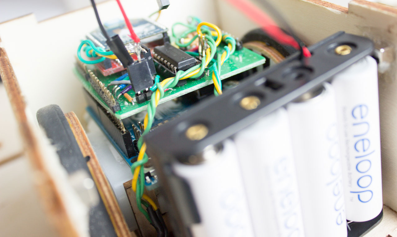
Now you can place the Arduino + Proto shield on top of the motors, plug all the headers on the shield and you have finished making Cubetto.